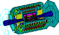
The FCal 1 Production Page
The construction of the Forward Calorimeter 1 (Fcal 1) is finally underway. All of the previous prototypes and Module 0 were leading up to this final production phase. In these pages you can follow along as we progress in the construction of the first Forward Calorimeter in the ATLAS experiment. The ATLAS experiment is one of two experiments for the European Large Hadron Collider (LHC) located at CERN Laboratories in Geneva, Switzerland. This page will be continually updated and under construction as we progress along the stages of production. There are two main areas of construction that our group at the University of Arizona will be working on, the mechanical detector Fcal 1 and the electronics for all three Forward Calorimeters in ATLAS.
- Work Flow Organization and Process Sheets
- Copper Matrix
- Copper Tubes
- Electrodes
- Construction Photographs of FCAL
- Miscellaneous Small Parts
- Cables
Forward Calorimeter Electronics
- Innerconnect Boards
- Summing Boards
- Front End Boards [FEB's]
The results from Fcal 1 Module 0 in Testbeam 98 were excellent and we have now begun to build Fcal 1, The Real Thing [TRT]. The following component parts of the Forward Calorimeter 1 will be detailed as to specification, modification, and use in final assembly. Check in on The Fcal 1 Assembly Page for progress in the final assembly of the Forward Calorimeter 1 detector. This page outlines steps and processes to assemble Fcal 1 from the component parts outlined below including construction of the cleanroom used for final assembly. -
The copper matrix of each side of the detector will be produced by stacking 18 1" thick plates with an outer diameter of 36" together. Each plate will have 12,250 holes, 5.75mm in diameter, arrayed in the 1" thick plate. Each of the plates must be made to exact specifications so that when all 18 plates are stacked the holes in each of them line up.
The actual machining of these plates is planning on being done by the University of Arizona's Instrument Shop with the use of a machine made by Monarch that we are currently under negotiations to procure for this project. Look for a link in this location later that will show pictorial progress on the machining of the copper plates, a project expected to take 18-24 months to complete.
Keep updated with the progress by visiting the Copper Matrix Home Page
-
The copper tubes required for this project are drawn, seamless tubes made from copper 122000. The dimensions specified for the tubes are, 445.00mm +/-0.250mm long with an outer diameter of 5.750mm +/- 0.013mm and a wall thickness of 0.250mm +/- 0.013mm. The contract to make these tubes has been awarded to Small Tube Products, PO Box 1674, Altoona, PA 16603. The tubes arrived here in Tucson on 28 September 1999.
|

Copper tubes
|
- Once the tubes are received we must prepare them for insertion into the copper matrix. Initially we will measure a sample of the tubes to arrive at statistical dimensions according to specifications. After measuring each tube will be deburred using a drill press and a bit designed to cut at a 60 degree angle. Then tubes will be put through rigorous cleaning procedures to assure a completely clean part for assembly into the Fcal 1 matrix.
- Keep updated with the progress by visiting the Copper Tube Home Page
-
-
The electrodes are made from the following component parts:
- Copper Rod
- Peek Fibre
- Signal Pin
|
![[Electrode Cartoon!]](images/Construction/electrode.jpg)
Cartoon of an assembled electrode
|
-
| The copper rods are made from C11000 copper H80 (hard drawn) and precisely ground to a diameter of 4.712mm +/- 0.005mm with a length of 445.00mm +/- 0.250mm. The bid for production of the copper rods for Fcal 1 has been awarded to Centerless Grinding Service, 1929 Sand St., Tucker, GA 30084-6632. The shipment of 26,500 rods arrived in Tucson in January 2000.
|
![[Copper Rods!]](images/Construction/rod.jpg)
Copper rods
|
-
| The insulating fibre we use between the copper rod and copper tube described above is made from monofilament peek with a diameter of 0.250mm. This fibre was produced by Zyex LTD in Stonehouse, UK. Click HERE for a microscopic view of the PEEK fiber.
|
![[Peek Monofilament Fibre!]](images/Construction/peekfibre.jpg)
Peek Fibre
|
-
| Each copper rod had a hole drilled in the center of one end and a signal pin was inserted into the hole. This forms the signal end of the electrode. After copper rods are deburred and cleaned [following the same cleaning procedures as for copper tubes] holes are drilled and signal pins inserted. The signal pins are Mill-Max part number 5601-0-01-15-0000-030. Click HERE to see a drawing of the mill-max pin in detail.
|
![[Pin Insertion into Rod!]](images/Construction/insertpin.jpg)
A signal pin being inserted into the end of a copper rod
|
-
Additional small parts include:
- Kapton Washers
- Brass Washers
- Ground Pins (Mill-Max pins identical to signal pins above)
- Sockets (Mill-max part number 0285-0-15-15-1614-100). Click HERE to see a detailed drawing of the Mill-max socket.
|
![[Washers, Pins, and Sockets!]](images/Construction/miscparts5.jpg)
Miscellaneous small parts used in Fcal 1
|
| The cables that will carry the signal from the mechanical detector to the electronics are specially made Kapton coated copper co-ax. These cables have been ordered from Axon' Cable, 1601 Feehanville Drive, Mt Prospect, IL 60056. Fcal 1 will require 128 cables with a length of 309 centimeters. We have ordered 141 cables to allow for spares. The cables are an important part of the detector and require several aspects of testing. Check in on the Cable Home Page for progress on the cable tests.
|
![[Kapton Coated Copper Cables!]](images/Construction/cables.jpg)
Kapton Coated Copper Cables
|
|


![]() Experimental Elementary Particle Physics Departmental Telephone: (520) 626-967
Experimental Elementary Particle Physics Departmental Telephone: (520) 626-967