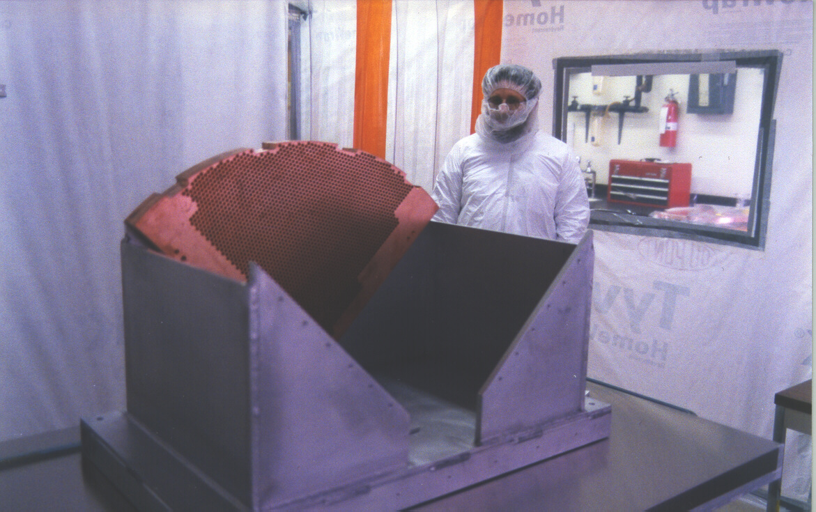
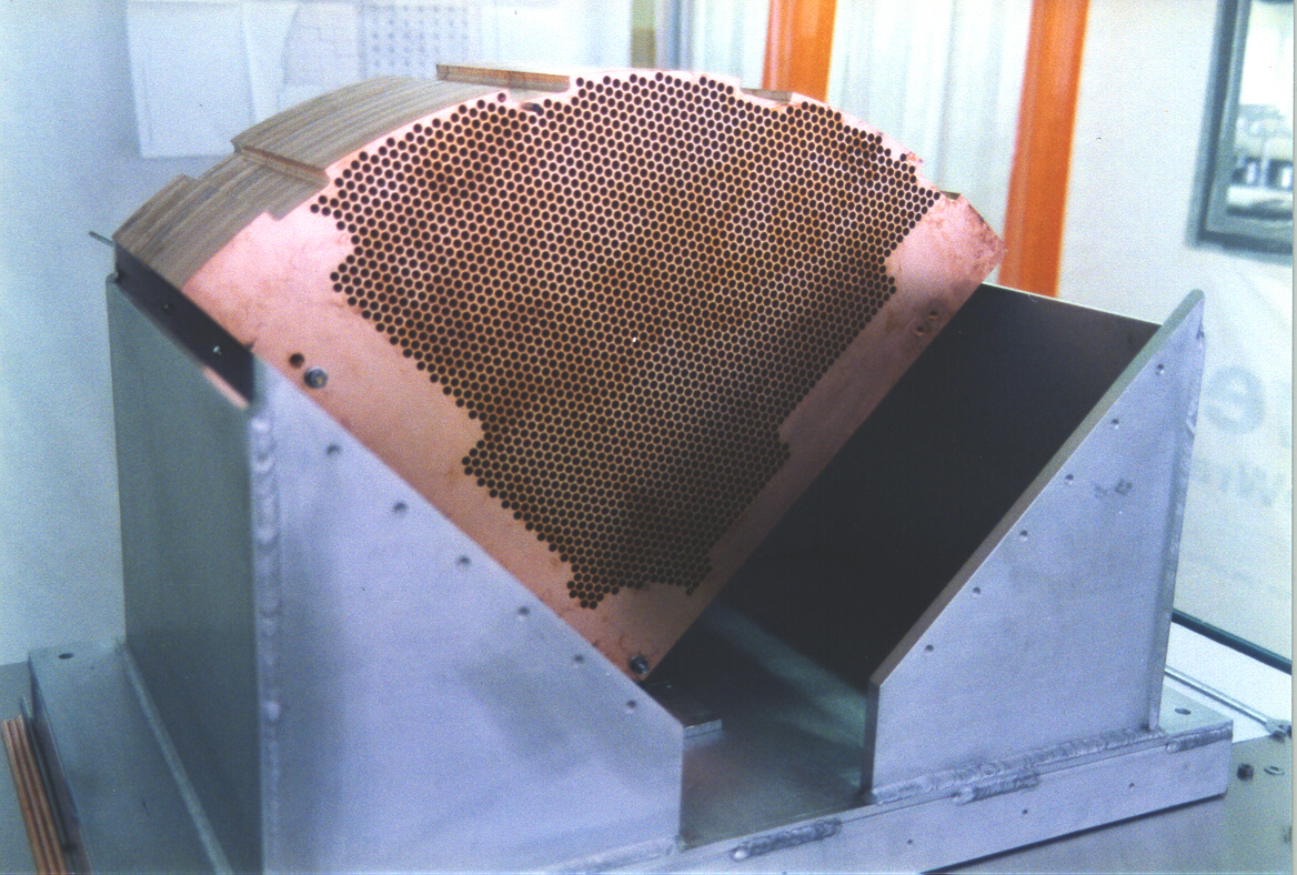
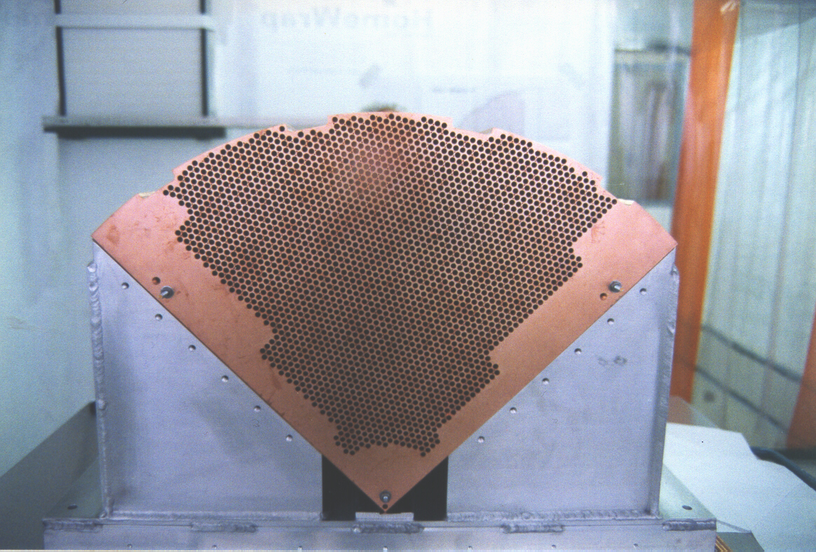
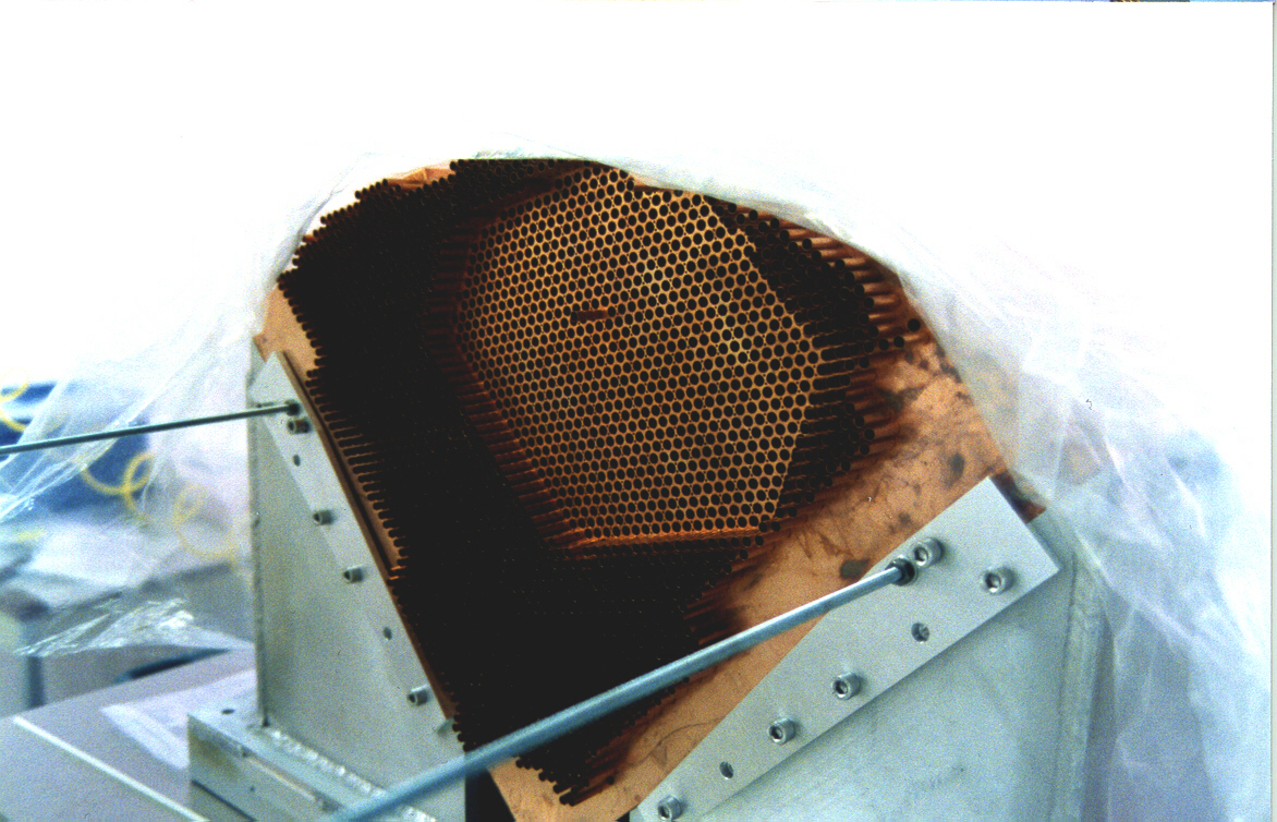
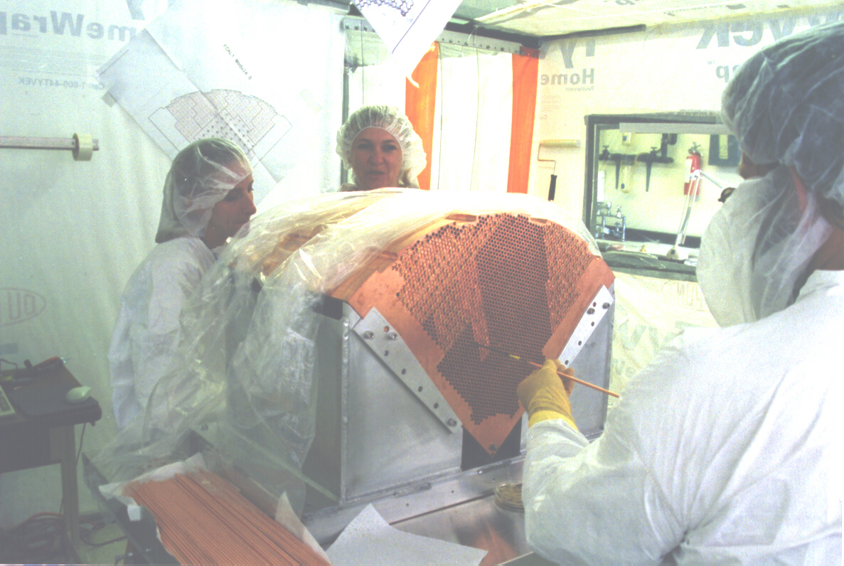
Initial Assembly
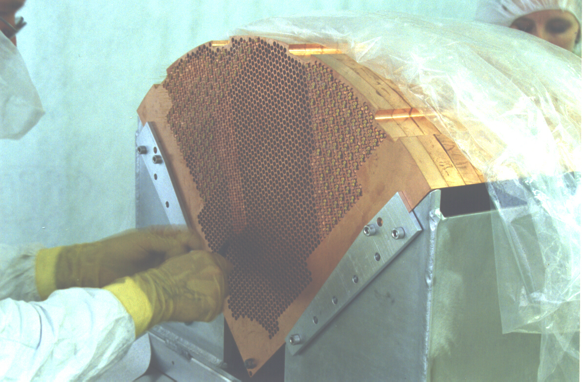
The assembly procedure began with the stacking of one endplate and 16 absorber plates into the carrier in the clean tent. Tube stuffing began. This procedure included evaluating the tubes for straightness, a final swabbing of the interior to ensure cleanliness, and insertion into the matrix. Tubes were inserted from the absorber plate end through the matrix to the endplate, and then made flush with the 16th, and final absorber plate. Once all the tubes were inserted into the matrix the the second endplate was added to the stack. All tubes were then pushed through the second endplate with the use of a tool to allow for even pressure over the tube as it was pushed into the second absorber plate. Tubes were then swagged at the front end[signal pin end] to ensure electrical contact with the tubes and the matrix.
Rods were drilled, prior to cleaning, for acceptance of the signal pin. Cleaned rods were bagged until signal pinning began. After signal pins were inserted into the rods they were bagged again and stored until electrode creation began.
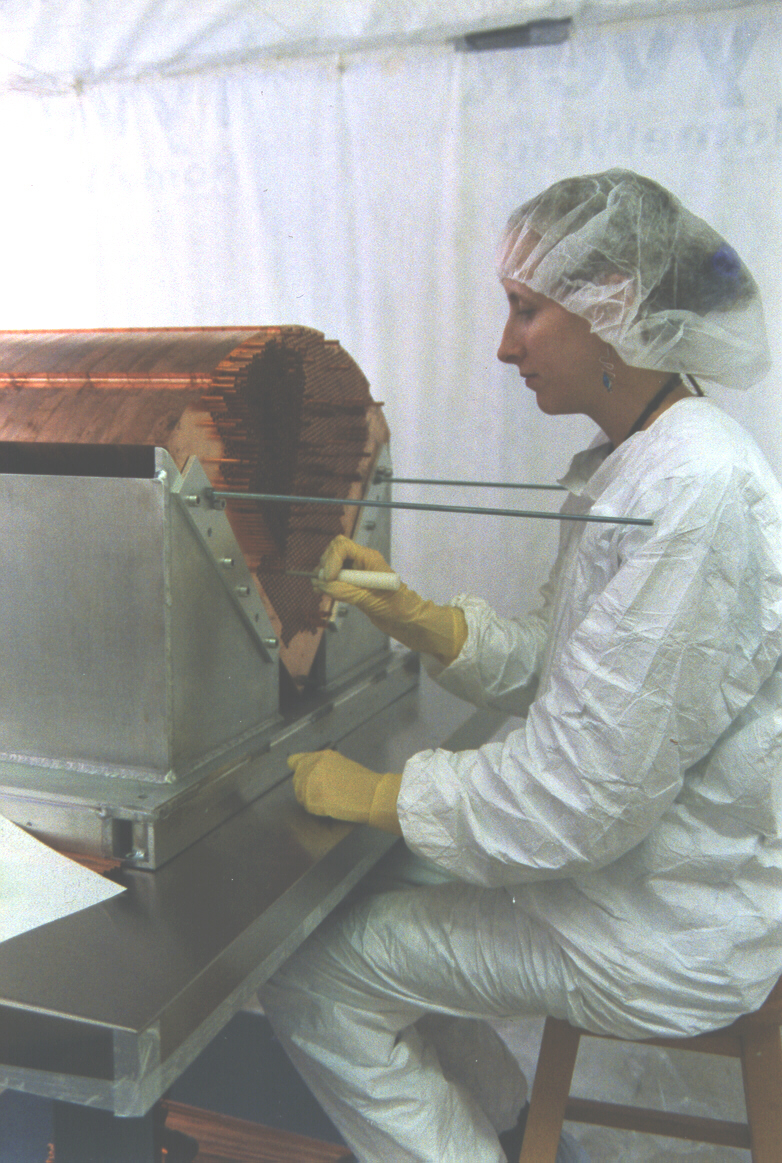
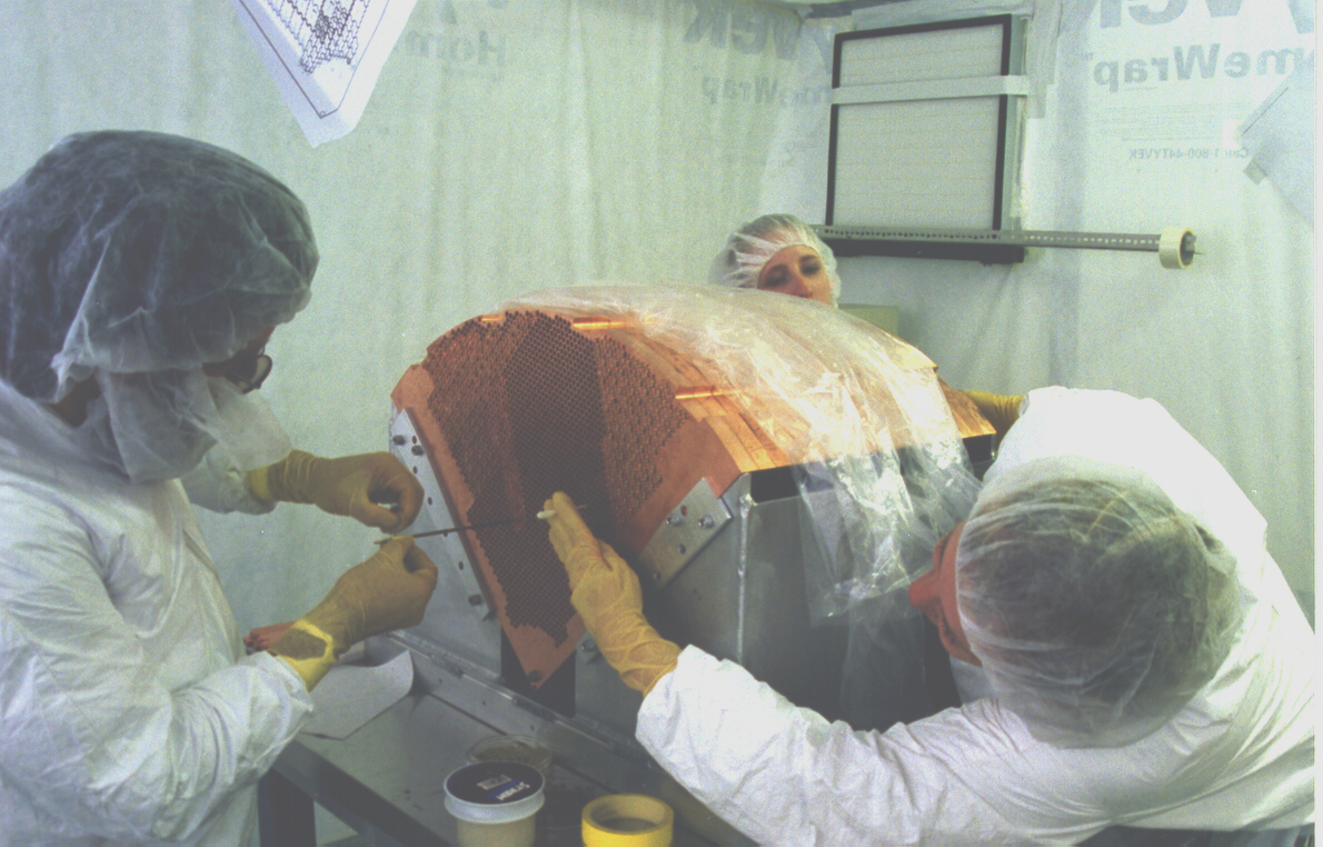
Tubes were swabbed a final time in small groups that were to be "stuffed" in a crew's shift. Tubes were then dried with nitrogen. Electrode assembly could then begin. Electrode assembly requires a crew of no less than 2 people, one on each end of the module.
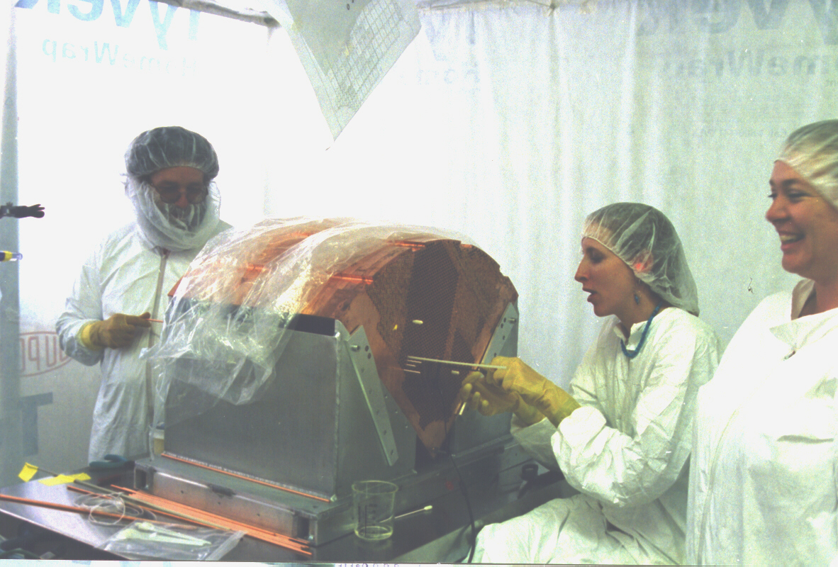
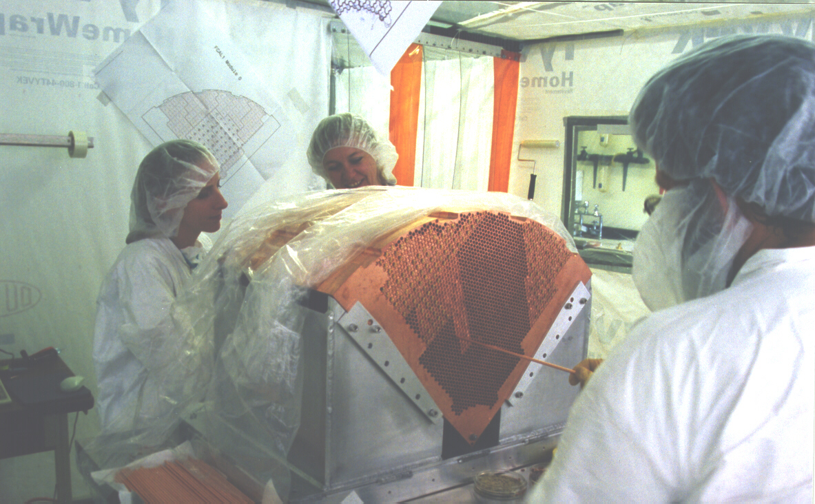
Electrode Creation
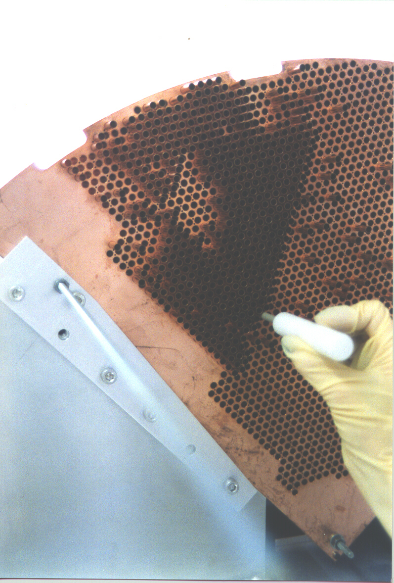
The person at the signal pin end would send the insertion tool through the tube to be assembled. The person at the "back end" of the module would then attach the nylon fiber to the insertion tool via electronics tape. Next, the signal pin of the rod would be inserted into the socket located on the end of the insertion tool. The rod's weight would be supported by one hand of the person while the second hand dealt with the fiber. The crew member at the signal pin end of the module would then slowly twist the insertion tool, causing the fiber to twist around hte rod. The person holding the rod and fiber would move her/his finger, which was between the fiber and the rod, down the rod. This spread the twists along the length of the rod. The person would tell the other crew member when to stop turning. Then from the back end of the module, the rod and fiber would gently be inserted into the tube. Once completely in the matrix, the fiber was cut on both ends, freeing the electrode from the spool of fiber and the insertion tool. Electrical continuity was then check as the preparation for the next electrode assembly took place. The process would be repeated if the continuity check failed.
Once a section was completed and passed the electrical continuity test then the ground pinning began. Each rod had the potential to escape the tube it was located in under tilting or shaking conditions , such as in shipping. Kapton washers with brass washers on top and held in place by a signal pine was the design. Two of these combos were done together allowing for maximum coverage.
A more thorough electrical test, as well as a capacitance measurement, were then completed on each electrode.
|